Quantcast
Channel: NI Reaktor Tutorials
Viewing all 150 articles
Browse latest View live

Introduction to FFT in Reaktor

$
0
0
In this original video tutorial we introduce you all to FFT, Fast Fourier Transform, and how it can be used to create effects like a vocoder!

Click here to view the video on YouTube.


Higher Math!

Using the EzFFT package in Reaktor can save you about 4 years of college math classes and help you design some very cool effects!

FFT, which is short for Fast Fourier transform, is an algorithm that is used widely in Science, Math, and Engineering. FFT can be a very intimidating thing for those of us who are not math gurus, but you will be happy to learn that there is an EzFFT package available for download over on the Native Instruments site. It is the same tool used in this video and will help you get a jump start on the ideas shared in the lesson. Simply put, it will allow you to break a sound down into its smallest components and then reassemble them in new ways. Luckily this user friendly tool makes it unnecessary to actually understand the complicated mathematics used to make it all work. So us mere humans can simply follow along with this great tutorial from salamanderanagram and make some cool new things to play with in Reaktor!

Salamanderanagram starts by briefly explaining the various FFT modules that are included in the download. He then shares how to use them in your own Reaktor creations by demonstrating the build of a nice little vocoder using the included modules. Putting conversion modules to good use, the hard work of translating out real and imaginary values into pitch and amplitude is made easy. Setting up the inverse modules is basically a duplication of the first set of steps. Once the basic structure of the FFT modules is in place for our vocoder, the work of fleshing it out into something more useful begins.

First a trigger to initiate the sample playback is set up. Then a basic sawtooth synth module is added to control the pitch of the vocoder. An amplifier unit is used to boost the decible levels and then the vocoder is routed to a single output making it a mono signal. After a quick test it is obvious that the simple sawtooth synth is not going to generate enough interest and character, so a Lazerbass module is used as the input synth instead. It also makes available all of the Lazerbass snapshots you have in your library. Which makes for a much more robust vocoder effect!

Have A Question Or Comment About This Tutorial?

Want to ask a question about this tutorial or perhaps you have something to add ?

Click through to our forum post about this tutorial and join the conversation!

Visit: Introduction to FFT in Reaktor

The post Introduction to FFT in Reaktor appeared first on NI Reaktor Tutorials.


Introduction to Reaktor Core, Part III

$
0
0
Welcome to the third installment of our series on programming in Reaktor Core. This time we’ll cover Quick Buses, the Sample Rate Clock, basic counter structures, and arrays. Let’s get started!
QUICK BUSES

One thing about programming in Core that I find makes everything much easier to keep track of is the QuickBus option. To create a new QuickBus, you can right-click on an input or output of any macro or module, and select the Connect to New QuickBus option:

For inputs, you will also notice the Connect to New QuickConst option. A Quick Constant is almost exactly like a regular Constant module, only it takes up much less space and can only be connected to a single input.
A Quick Bus is connected to a single output of a module, and can connect to as many inputs as you like. They function exactly like normal connections via wires, but can look substantially cleaner:

You can change the name of a Quick Bus in the properties.

Don’t underestimate how useful this is! Not only does the Quick Bus make the code look cleaner, it also makes it much easier to come back to a project later on and figure out what each piece of code does. A well organized Core Cell can be re-used later on, and appropriated for new purposes. Poorly designed code simply looks like nonsense if you spend more than a few days away from it, and is unlikely to be used more than once.

You’ll find that I use Quick Buses very often.

THE SAMPLE RATE CLOCK

The inputs to any macro or module can also be connected to the Sample Rate Clock (SR.C). To do so, simply right-click on any input and select the Connect to SR.C option.The SR.C is an event source that fires an event for every tick of the audio clock. So, if the sampling rate is 44100 Hz, the SR.C will fire 44100 times per second (the event values themselves are undefined, used mainly to trigger Read and Write modules, as we will see below.

These events happen simultaneously with any events caused by audio rate inputs in Audio Core Cells (simultaneous events were described in an earlier tutorial in this series).

Please note that while this option is available in Event Core Cells, the SR.C will not actually do anything inside of an Event Cell, so make sure to use them for Audio Cells only.

Directly beneath the Connect to SR.C option, there is another option, Connect to SR.R. SR.R functions identically to a Quick Constant with a value equal to the sampling rate.

COUNTERS

A very common element in Core design is a counter. Counters can easily be modified to create phase accumulators for oscillators, timers for envelopes, index counters for delays, and many other useful DSP elements. I’ll be using both the SR.C and Quick Buses in this example.

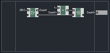
Here is the most basic counter available:

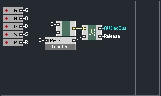
This structure simply outputs the number of samples that have occurred since the ensemble was opened. This structure can be modified to reset the count very easily:

The Reset input triggers a Read module. Since the Read module is not connected via a Latch input to any other module, there is no way to write to that particular value, hence the value get initialized to zero and stays there. The Read module feeds directly into the Write module, which is connected via a Latch to the other modules in the macro, so they all share a value. This achieves the task of resetting the counter to zero.

Note that the Count value is simply sent directly to the output before adding 1 to the value. The reason for this is simple. The reset will most likely occur as an event being sent from Primary. Since events happen in between the ticks of the audio clock, the first output of this counter after a reset will be a zero.

If the trigger to reset happens to be an audio signal, the events happen simultaneously, or in this case, in an order specified by the latch connections. Thus, the value is written to zero, then read and output, then added to 1 and stored for later use. Either way, the first output after a reset is always equal to zero.

This type of counter is similar to what you would use to keep track of time in an envelope structure, for example.

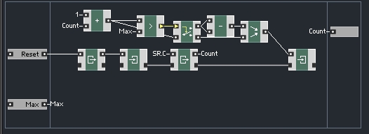
The counter can be further modified to output values only within a certain range, looping through those values instead of increasing permanently. This can be done in any number of ways, according to the user’s needs, but here is a basic example:

The value Max is chosen by the user and represents the maximum value to output. This type of counter can be used for Delay lines, amongst other purposes. The Count+1 value is routed to either subtract itself (IE restarting at zero) or simply be passed directly to the Merge module.

ARRAYS

An Array module is used to store values. They can be used for many of the same purposes as a Primary Event Table or Audio Table. Arrays have an advantage over those modules, however, which is a far more flexible design for writing and reading values.

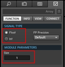
You can set the number of variables an Array can keep track of at once in the properties:

You can also choose whether the Array module will store integers, or floats.

The easiest way to interface with arrays is to use two macros from the Expert Macros -> Memory menu: Read [] and Write []:

These macros work similarly to the Built-In Modules Read and Write that we went over in the previous tutorial. The main difference is that with Arrays you also need to supply an index value to tell Reaktor which variable to read or write.

Like before, the latch inputs and outputs can be used to force an order of operations in structures that may otherwise be vague due to Core’s simultaneous event processing.

That’s all for this week, in the next tutorial, we’ll finally get into building some structures using the concepts we have learned so far.

Have a Question or Comment About This Tutorial?

Want to ask a question about this tutorial or perhaps you have something to add?

Click through to our forum post about this tutorial and join the conversation!

Visit: Introduction to Reaktor Core, Part III

The post Introduction to Reaktor Core, Part III appeared first on NI Reaktor Tutorials.

Building an Envelope in Reaktor Core, Part I

$
0
0
In this tutorial series, I’ll focus on building an envelope in Reaktor Core. Readers of this series should have a decent understanding of the Core environment. You can read this series of tutorials to get yourself up to speed if necessary.

ENVELOPE FUNDAMENTALS

To begin with, let’s take some time to talk about what an envelope is and how it works. Obviously this is the first step to building just about anything from scratch in Reaktor. In this tutorial we’ll be focusing entirely upon a standard ADSR envelope design. This section will probably be incredibly boring if you have a strong knowledge of envelope architecture!

While envelopes can be used for several purposes, such as modulating the cutoff frequency of a filter, they are most commonly used to control the amplitude of another signal, generally audio oscillators.

The first phase of an envelope, called the Attack phase, is triggered by the start of a new MIDI note. The amplitude of the envelope at the beginning of a new Attack stage should simply be the last value output by the envelope. This may seem counter-intuitive, as generally the Attack stage is thought to start from an amplitude of zero and rise to the maximum amplitude, which is controlled by the MIDI gate.

However, there is the possibility that a new MIDI gate arrives before the previous envelope is finished with it’s Release stage. In this instance, restarting from zero will create a ‘click’, which sounds distinctly like a digital glitch (and not a good one), as the envelope jumps from it’s previous value directly to zero. So, we re-start the envelope from it’s most recently sent output, which should usually be zero anyway.

The Decay stage simply decreases from the maximum amplitude to the amplitude chosen by the Sustain knob. Since the Decay stage only begins at the end of the Attack stage, it is quite simple to implement.

Not as simple as the Sustain phase, however, at which point the envelope simply outputs the value given by the Sustain knob.

Finally, we have the Release section, which is sort of an inverse of the Attack phase. The Release section is triggered by the release of a MIDI note. It travels from the most recently output value (often the Sustain value) back to an amplitude of zero. While the Release is usually thought of as starting from the Sustain value, it is quite possible that the MIDI note is released before the envelope reaches that stage, so we can simply use the last value output from the envelope as the start of the Release stage.

The last thing I want to cover in this section is the four knobs that the user uses to interface with an envelope – Attack, Decay, Sustain, and Release. The Attack, Decay and Release values control the length of each section in time (we’ll be using milliseconds). The Sustain knob, meanwhile, is an amplitude value.

CORE IMPLEMENTATION

We should be able to implement all 4 envelope stages using a single time counter, as outlined in Part III of the Introduction to Reaktor Core series:

This counter counts the number of ticks of the sample rate clock. I have modified from the previous version to deal with integers only. This is not strictly necessary, but it is slightly faster.

This counter restarts from zero at every incoming event to the ‘Reset’ input. When we connect the incoming MIDI gate to the Reset input, the counter will restart every time a new MIDI note is pressed, and every time those notes are released.

We can then use the state of the gate input in conjunction with the output of the counter to decide where to route the counter value. For example, if the gate is on, we know that the value needs to be routed to either the Attack, Decay, or Sustain stages. If the gate is off, we know it can go directly to the Release stage:

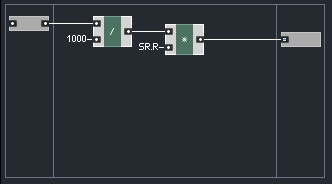
Next, we’ll take the Attack and Decay times, and calculate their length in samples. For example, if the Attack is 100 milliseconds long (1/10th of a second) and the sample rate is 44100, there are a total of 4410 samples in 100 ms (1/10 * 44100):

I rounded the output to the nearest integer value, this way each stage takes a certain number of sample ticks, with no annoying fractional values, such as an attack time taking 101.45 samples.

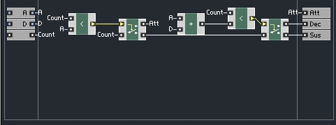
If the gate is on, we can use these value to determine which stage is currently active. If the counter is less than the number of samples in the Attack stage, then the Attack stage is active. If not, we check if the counter is less than the Attack stage length + the Decay stage length.

Using this information, we can choose which output to send the counter value to:

The counter value will be used as a clock for whichever macro receives it. In the next tutorial, we’ll design the envelope stages so that they only output a value if one is received to the clock input. Then we can simply merge together the outputs of the stages and we’ll have a functioning ADSR envelope.

CONCLUSION

It may feel as though we’ve accomplished very little, for the length of this tutorial, especially given that the counter was mostly done in the Introduction to Reaktor series. However, we have accomplished much in that we have outlined the problem and have a large view of how to solve it.

The reality is, we’re quite close to being done! Join us next time, where we’ll get into designing a function that can be used for the Attack, Decay and Release sections. Thanks for reading!

Have a Question or Comment About This Tutorial?

Want to ask a question about this tutorial or perhaps you have something to add?

Click through to our forum post about this tutorial and join the conversation!

Visit: Building an Envelope in Reaktor Core, Part I

The post Building an Envelope in Reaktor Core, Part I appeared first on NI Reaktor Tutorials.

Programming and Design in Reaktor

$
0
0
This week, I’m taking a break from tutorials on the Core environment. Instead, I’ll go over another commonly requested topic – overall programming and design in Reaktor. I’ll be discussing things like planning out an ensemble from scratch, my general workflow for creation, GUI design, and whatever else comes to mind.

START SMALL

One of the most common design flaws that many beginners are drawn towards is over-complexity. Certainly we’ve all probably had the experience of wishing that a given synth had an extra filter or LFO. Thus, many Reaktor beginners have an idea in their head for a ‘mega-synth’ with 16 LFOs, tons of modulation options, and all sorts of bells and whistles.

Unfortunately, these projects often collapse under their own weight. If you don’t fully plan out a project, you may find out after putting a lot of work in that something needs to be completely re-designed to accomodate a new feature you want to add. With the huge modular synths that people like to design, it is very very hard to think of everything you want to do before you start building.

Therefore, it is often best to create the smaller components of a project first. For example, if I want to design a synth where any knob can be controlled by a variety of modulators, the first thing I do is design a custom knob macro, with a built in Receive object to control the modulation.

Done right, it may take a few days to do something this simple – depending on the feature set you want and the amount of patience you have! For example, if you want to build a knob that acts like the knobs in Massive (the standalone Native Instruments synth, not the Reaktor ensemble) there are many things to implement – most importantly the ability to display and change the amount of modulation, and to be able to connect easily to any modulator. Further, you’ll probably need to design your own graphics, which can be time consuming and frustrating as well.

Knobs with built-in modulation routing. They took a few days to design properly.

Of course, many fantastic ensembles have been build simply using the built-in knobs that Reaktor comes with. The idea here is to choose a small part of your system to work on at a time and make it work perfectly before moving on. Many times, this will mean designing a proof-of-concept for your audio engine, then adding in new features as you refine your work.

Take it slow, take the time to really think about what you’re trying to accomplish, make sure you design things right the first time, and you’ll save yourself a lot time and effort.

KEEP IT CLEAN

If you’ve read any of my previous tutorials, looked at my ensembles or watched my videos you’ve probably noticed I have a tendency to keep my code looking very neat. This does have an important purpose, which is to keep my work easy to read when I come back to it weeks or even months later.

Even if you treat it like a full-time job, designing a full-fledged Reaktor project takes a long time. Dirty code is hard to read and that can make an entire portion of your code a mystery to it’s own designer!

Another thing to keep in mind is you should use macros whenever necessary, both to keep your code clean and to compartmentalize different tasks. When each piece of code is neatly separated, it is easier to find bugs as well.

For example, a series of event modules that confines a value to a certain range using Separators, Values, and Merge modules will be more confusing to ‘read’ two months later than a macro named ‘Clip’ with Min, Max, and Value inputs. You can even use the ‘INFO’ tab in the macro properties to store a little information about how a macro works.

TEST YOUR WORK!

When building components that are meant to be used repeatedly throughout an ensemble, it is very important to test them thoroughly first! Unseen errors are most likely to propagate via event modules, which are often poorly understood.

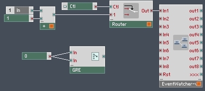
You can use the Event Watcher macro by Chris List to test the behavior of any (monophonic) event stream. Used in conjunction with a Switch module anywhere in the enesemble, you can test how your simple macros respond to a Global Reset Event (GRE):

Any event based module you design to be used in numerous places should be tested in this manner. The other option is to design your ensemble to avoid GREs altogether, which is often quite difficult or functionally impossible to achieve due to CPU or other concerns.

By thoroughly testing you work before propagating it throughout an ensemble, you save yourself the headache of having to track down and delete or edit every instance of a macro later on.

THOUGHTS ON GUI DESIGN

There are a few things to keep in mind when designing a GUI for a Reaktor project. You want to keep the controls simple and well organized for the end user. This means placing controls that are related next to each other on the panel. It is also important to sometimes make tough decisions about which controls you need to have and which controls you don’t.

If you want to make a plethora of options available for your users, it can sometimes be helpful to use Stacked Macros to fit a large amount of controls into a small amount of space.

However, I suggest trying to avoid an overabundance of controls if possible. Keeping your panel compact makes the controls more accessible to the new user (and those with small screens!) – they don’t have to look everywhere for what they want because it is right in front of them.

If somebody can easily grasp a new interface and get good results out of it quickly, they are much more likely to stick around and keep using it.

CONCLUSION

Well, I’ve barely had time to scratch the surface of this huge topic. Let me know if there is interest in more and I will surely make it! Next week we’ll return to our regularly scheduled Core tutorials.

Have a Question or Comment About This Tutorial?

Want to ask a question about this tutorial or perhaps you have something to add?

Click through to our forum post about this tutorial and join the conversation!

Visit: Building an Envelope in Reaktor Core, Part I

The post Programming and Design in Reaktor appeared first on NI Reaktor Tutorials.

How to Build a Stutter Glitch Effect in Reaktor

$
0
0
In this original tutorial, Salamandaranagram shares how to build a cool stutter glitch effect using Reaktor!

Click here to view the video on YouTube.


Controlled Chaos!

Building an effect like this stutter glitch unit is much easier than you’d probably expect!

This Stutter Glitch effect is based upon a simple design of a Crossfade module receiving audio which is then routed directly into a Single Delay unit. This, in turn, is routed back into the Crossfade unit before hitting the main output. This set up is then duplicated so there is audio for both right and left channels. Now that the core of the stutter glitch effect is built, tempo information is introduced so we can control the delay properly within Reaktor. Once the Selector module is in place, the different tempo sync options can be added. A Multi-text tool is used to display the different tempo sync options on the main interface.

Now comes the process of making it all look nice! When you add multi-text options to the interface it can quickly become a mess. Follow the tips shared in the lesson to achieve the same clean look that Salamanderanagram ended up with. This will give you an interface with a knob that twists to change the tempo sync settings. If you prefer that MIDI actually triggers changes in the tempo sync setting, simply apply the same changes that are made in the second half of this video. It’s a simple effect to build, once you wrap your mind around how it all works, but it delivers a very complex sounding result. A perfect choice to help you on your path to learning how to create things from scratch in Reaktor!

Have a Question or Comment About This Tutorial?

Want to ask a question about this tutorial or perhaps you have something to add?

Click through to our forum post about this tutorial and join the conversation!

Visit: How to Build a Stutter Glitch Effect in Reaktor

The post How to Build a Stutter Glitch Effect in Reaktor appeared first on NI Reaktor Tutorials.

Building an Envelope in Reaktor Core, Part II

$
0
0
In this tutorial, I’ll continue building an envelope in Reaktor Core. In the previous tutorial, we laid down the groundwork for building an envelope – a router macro that determines which stage of the envelope is currently active.

For those who are unfamiliar with the Core environment, there is a three-part series on that serve as an introduction here.

IMPLEMENTING THE ENVELOPE STAGES

The Attack, Decay, and Release stages of an envelope all have several things in common structurally. Each one has a starting point, an ending point, and a time that determines how long it takes to move from the start to the finish. In addition, each of these stages has a single output that is somewhere between the starting point and the ending point, and receives a clock input from the larger structure that determines when the stage is active.

Envelopes

The Attack, Decay, and Release sections are identical

The Sustain stage could also be implemented in this way, in theory, with a starting point equal to the ending point, and an arbitrary length of time to travel between the two. However, such an implementation would be wasteful – we’d be calculating unnecessary math whenever the Sustain stage was active. Instead, during the Sustain section, the value of the Sustain knob can simply be stored and sent to the output. In fact, you’ll see later that we can actually ignore the Sustain section altogether!

Okay, let’s get down to brass tacks. We can begin by creating a simple black box version of the Attack, Decay, and Release stages that I outlined above:

Since we’ve already calculated the length of each stage in terms of the sampling rate, let’s assume that the ‘Time’ input is also measured in samples. The ‘Clk’ input, aside from letting us know that the stage is active, also keeps track of the number of samples that have occured since the last MIDI gate value has arrived (both gate on and gate off messages will reset the counter, which is useful for the Release stage).

Therefore, we can fill in our black box macro from above to look something like this:

Keep in mind that this macro should only send a value to the output when a value arrives at the ‘Clk’ input. Therefore, the final calculated value is stored in a latch macro (found in the Expert Macro menu, in the memory section) which is triggered by the incoming clock.

Mostly, our work now becomes simply plugging in the proper values to the inputs of this macro. We outlined many of the specifics in the previous tutorial. For instance, rather than restarting from a value of zero every time, the Attack section can actually use the last previous output from the envelope as it’s starting point. Generally this will be zero, however, in case the envelope is triggered before the previous note is finished, this method will prevent a ‘click’ sound.

Here’s a view of our final Core cell:

Utilizing the basic structure that was designed for last weeks tutorial, we have simply plugged our new envelope stage macro in place and merged together their outputs (only one will be outputting values at any given point in time). A new gate input triggers many things, controlling the start values of all three stages (depending on whether the gate is on or off) and the end time of the Attack stage.

Notice here how the Sustain stage is simply ignored entirely. The reason for this is simple – we don’t need it! Once the Decay section is complete, the envelope is already at the value determined by the Sustain knob. Since the output is already the value we want it to be, we simply do nothing until we receive a Gate off event and begin the Release stage.

CONCLUSION

Alright, so now we have a working envelope. It is nothing special, of course, and there are many improvements that could be made. For one, this envelope has linear growth and decay, whereas higher quality envelopes generally use exponential curves for the stages. Other features could include: a peak knob that determines the maximum level of the envelope Attack stage; a maximum velocity option to always treat incoming gates at their maximum possible value; adding a looper like the envelopes in Ableton’s Operator synth; a GUI for controlling and visualizing the resulting envelope; etc.

If there is interest, we can cover some of these options in a future tutorial.

Have a Question or Comment About This Tutorial?

Want to ask a question about this tutorial or perhaps you have something to add?

Click through to our forum post about this tutorial and join the conversation!

Visit: Building an Envelope in Reaktor Core, Part II

The post Building an Envelope in Reaktor Core, Part II appeared first on NI Reaktor Tutorials.

Custom GUI in Reaktor, Part I

$
0
0
Creating a unique and responsive custom GUI in Reaktor is an important part of making an immediate impression on your users. In this series, I’ll go over a variety of ways we can improve upon Reaktor’s default knobs, in order to create a better user experience.

CREATING CUSTOM SKINS

The easiest way to make your work stand out is to create your own custom UI elements – the default Reaktor knobs are pretty boring and generic.

Pro Tip

Use Knobman to create custom GUI elements

Unfortunately, Reaktor does not come with a tool to help you design your own controls. However, there is a wonderful free program designed specifically for the creation of custom GUI elements called Knobman, which you can download here.

A tutorial on Knobman is beyond the scope of this article (and this website), but you can find a simple intro here. It’s pretty simple to get the basics.

Once you have a new skin, you can make a knob use that picture in the VIEW tab of the properties:

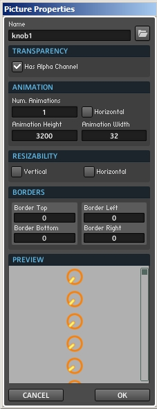
This brings up a window where you can specify the height, width, and number of animations in the knob:

Once a skin has been loaded into an ensemble, you can also select it directly from the Skin Bitmap menu, saving the step of specifying the height, etc.

PLAN AHEAD!

An important thing to consider about your GUI is that often you want to be planning pretty far ahead. For instance, if you want your knobs to behave in a specific way that requires a little extra programming, you’ll probably want to design a knob macro before getting too deep into the project. This saves you the effort of having to replace each knob manually later on.

Even if you are simply going to design a skin for your knobs, you can save yourself a lot of time this way. Imagine you have a synth with 40 or 50 knobs. If you wait until the end of the building process to skin your knobs, you’ll have to change the bitmap for each knob individually!

In contrast, if you create a placeholder skin early on, you can create a knob using that skin. Then create any other knobs by duplicating a knob with the placeholder skin. At the end of the project, you can refine your skin. Then, by selecting the ‘Picture Properties’ option in the Skin Bitmap menu in properties,

you can change the look of all knobs in your project at once! This is really very helpful when you want to tweak a knob’s skin without reloading the graphic dozens of times.

EXPANDING FUNCTIONALITY

By default, Reaktor’s knobs only respond to left clicks on the mouse, and events are only sent when a knob’s value is changed. This works fine in many instances, but other times it leaves something to be desired.

For example, I like to create custom knobs with no numeric display attached. I find that the displays take up space and often display information that is quite useless to the user. An attack knob for an envelope, for instance, displays little of use to the user, unless that user is versed in translating from the logarithmic scale into milliseconds.

So, instead of displaying the value of each knob directly below the knob graphic, I like to use a single numeric display that only shows the most recently used knob. In a sense, this is simple – you can simply merge together all of the values from knobs in the ensemble, and the most recently sent value will be displayed:

The problem is that, as I mentioned above, knobs only send events when their value changes. Therefore, simply clicking on a knob will not be enough to display it’s value in this setup, the user will actually have to change the value in order to see it. This is clearly not optimal behavior.

A trick I like to use to expand the functionality of the Knob module is to layer a Mouse Area directly over the knob itself. In this picture, I’ve turned down the transparency on the mouse area so you can see what I mean:

Make sure the knob and the Mouse Area are about the same size. For default Reaktor knobs, I use a height and width of 40.

As long as the knob is in the same macro as the Mouse Area, whenever you click on the knob in the panel, the Mouse Area will receive the data instead. So, you must use the Mouse Area to control the knob, which can be very easily achieved using an IC Send module. Connect the IC send to the knob using the CONNECT tab of the properties.

An important part of this structure is that you must set the ‘Incremental Mouse Mode’ to be on in the properties of the Mouse Area.

In the above picture, the Mouse Area controls the knob whenever the left mouse button is active. We can easily extend this structure so that a new mouse button also reads out the knob value, sending it to be displayed regardless of whether the knob value changes or not:

And we can merge the outputs of these macros together to be displayed:

Another advantage of this setup is that we can use the right and center mouse buttons for other purposes, such as setting up modulation routing for that specific knob.

In this section, we see very clearly the reason for planning ahead and deciding upon the functionality you want for your GUI before you get too deep into building – obviously replacing every knob in a large ensemble with one of these macros is a huge pain that can easily be avoided by careful planning.

CONCLUSION

We have just scratched the surface of this topic – creating a good GUI is on of the harder things to do in Reaktor, requiring a great deal of patience and planning, as well as a solid understanding of the Panel modules. There is much more we could cover on this topic, please let me know if you are interested!

Have a Question or Comment About This Tutorial?

Want to ask a question about this tutorial or perhaps you have something to add?

Click through to our forum post about this tutorial and join the conversation!

Visit: Custom GUI in Reaktor, Part I

The post Custom GUI in Reaktor, Part I appeared first on NI Reaktor Tutorials.

Phase Modulation in Reaktor

$
0
0
In this tutorial we see how to build a Sine wave oscillator that allows for phase modulation, made entirely from scratch inside Reaktor!

Click here to view the video on YouTube.


Phase Modulation!

Often mistaken for FM Synthesis, Phase Modulation is a very cool way to design new sounds!

Salamanderanagram is back with another great tutorial. This time we get to see a new kind of Sine oscillator being built from scratch. This oscillator will allow for phase modulation, a type of modulation that is very similar to frequency modulation and has been mistakenly believed as FM modulation in numerous popular synths over the years. It’s a fascinating topic and neat to see the instrument come together one piece at a time. Let’s go ahead and see how it’s done.

First a basic Sine oscillator is built to be used as a comparison test module. As the designing of the new phase modulation model is built, it can be tested against the basic Sine oscillator to make sure it’s all coming together without any issues. This approach does take a lot more power to run, but it also ensures a more successful and accurate design in the end.

Use of the Modulo module is key to making this oscillator work. It keeps the signal identical to what was originally being produced by the ramp oscillator earlier in the signal flow. For those who have not fully understood the function of the Modulo tool in the past, you may want to check out this tutorial from Mike Huckaby trying to break it down into more understandable terms.

Once you have successfully tested the new phase modulation oscillator against the test sine oscillator, you can remove the unnecessary primary sine oscillator. Now the process of making a simple phase modulation synthesizer can begin. Add envelope controls, as well as pitch and phase modulation control, and you are well on your way to creating something that is not found in the Reaktor factory content!

Have a Question or Comment About This Tutorial?

Want to ask a question about this tutorial or perhaps you have something to add?

Click through to our forum post about this tutorial and join the conversation!

Visit: Phase Modulation in Reaktor

The post Phase Modulation in Reaktor appeared first on NI Reaktor Tutorials.


Understanding Stacked Macros in Reaktor

$
0
0
Learning how to use Stacked Macros can open a whole new world of Reaktor. This video tutorial was made especially for our members who are looking to push the limits of Reaktor and begin unleashing more of its hidden potential!

Click here to view the video on YouTube.


Multi-Macros!

This Reaktor tutorial shares how to create a multi-mode filter by using stacked macros!

We’ve come to learn something about Reaktor since we started up this website and community. If you have a complex question about Reaktor, ask the guru salamanderanagram! In this lesson he tackles the question of how to stack macros within Reaktor to combine their capabilities in order to build even more impressive ensembles, specifically how to build a multi-mode filter unit. He starts with an empty Macro, and inside of that Macro he adds a Pro52 Filter. After some quick wiring and setting up some knobs, he explains that you can actually make filters visible in your finished ensemble interface.

The next step is to duplicate the Macro that was just set up. Double-click it to see inside, and then select and remove the Pro52Filter. A new Ladder Filter is now added to the now empty Macro. Go ahead and use the pieces already in place to get it wired up and you now have a second filter macro finished. Within the Properties window, this filter is also made visible. These stapes are repeated again, duplicating the last macro, deleting the Ladder Filter and replacing it with a Multi-Mode 4Pole Lowpass Filter, get it wired up and set it to be visible. The entire process is done once more, this time around a Highpass Filter is used.

Now you have four Macros build that are identical except the kind of filter that is inside each one. Switching now from Structure View to Panel View, you can set up the interface the way you like it by using the Edit Panel mode. Once done, you should be able to see all four filters in the same interface and the two knobs should be controlling all of the filters simultaneously. Now we jump back into Structure View and place all four of the Macros we made earlier inside of a Stacked Macro module. This will make it so we can use and see one filter at a time in the main interface. A Switch and List are then added so we can toggle between filter macros. Go back into Panel View and arrange the interface to your liking, and that’s it!

Have a Question or Comment About This Tutorial?

Want to ask a question about this tutorial or perhaps you have something to add?

Click through to our forum post about this tutorial and join the conversation!

Visit: Understanding Stacked Macros in Reaktor

The post Understanding Stacked Macros in Reaktor appeared first on NI Reaktor Tutorials.

Arrays in Reaktor, Part I

$
0
0
In this tutorial, I’ll be starting the creation of a framework for the use of arrays in Reaktor. Arrays are a part of the Core environment, and as such the reader should have a decent familiarity with Core. There is a series of tutorials here to help you get your feet wet.

As is often the case, Part I of this series is a little slow, as I explain the purpose of the project and the problems we will encounter. Next week we’ll pick up the pace some, I promise!

CORE ARRAYS

An array is a module that can be used to store a large number of values. Arrays can have any number of uses, but a common one is storing incoming audio into a buffer for later use, such as in a delay line.

In Reaktor, there a number of ways to store large amounts of data – the Event and Audio Tables, the Tapedeck modules, and Core Arrays. While the other modules have their purposes, Core Arrays are more powerful than their Primary counterparts in that they allow for multiple access points of data, and can force an order of operations that would be difficult to replicate in Primary. We’ll get into why that’s important in just a bit.

Pro Tip

Core Arrays can be more powerful than their primary counterparts

There are several ways that a programmer may wish to manipulate data in an array. Examples include adding new values, deleting old ones, inserting values in between existing values, sorting data (such as from highest to lowest), etc.

Unfortunately, shortcomings within the Reaktor environment make many of these basic operations quite difficult. It is my intention to create a simple framework to manipulate data in this tutorial series. Eventually, I hope to use the framework to create a multi-breakpoint envelope, where the array holds information about the number of stages the user has specified.

It will be necessary to allow the user to delete and insert data points at will for this project, which makes it a perfect fit for the data framework I would like to build. If you are unfamiliar with the concept of a multi-breakpoint envelope, you can check the macro “Multi-BP Env” in Reaktor, or if you have Absynth, the envelopes in that are another example. There is also a tutorial series on envelopes here that fully outlines the different stages of an envelope.

Let’s tackle the different types of data operations one by one.

ADDITION

Adding a new element to an array can be done in any number of ways. There is a distinction between adding a new element to the end of an array (called adding) and adding a new element somewhere that another element is already stored (called insertion).

Adding is the simplest of our data operations, so we’ll tackle it first. I often like to start such a project by imagining a ‘black box’ macro that has inputs for each piece of information I need to accomplish something, and whatever outputs are necessary:

To add a new element, we need the value we want to add to the array, the current number of elements stored, and access to the array itself. The outputs are simply updated versions of the Idx and Data inputs. If data operations need to be done in a specific order, the outputs can be used to control the inputs of other macros, as we shall see eventually.

Now let’s think about what the inside of this macro should look like. We have a value (Idx) that gives the current number of objects stored in the array. We want to store the data in that index, and then increase the value of Idx by 1 – for example, if there are no elements currently stored, we store at index 0, then add 1 so the next element will be added at index 1.

Each event arriving at the value input will store to a new point in the array. One caveat is that the array must be large enough such that the value of Idx is not out of bounds. If Idx is greater than the array size, the data will overwrite the last element.

The easiest solution to this is simply to create an array way larger than you need – for example, if the array can hold 5000 elements, it seems unlikely that anybody would take the time to create that many stages of a multi-breakpoint envelope. If, for whatever reason, this is not a workable solution, you can also modify the structure slightly:

In this example, if there is no space left in the array, the input is simply ignored. Another common way to handle this problem is to simply wrap around the structure, so if the index is too large, simply start writing over the beginning of the array again. This type of array write is used quite commonly, especially with delay lines.

Despite being very similar, these are three distinct macros that can be used for different purposes. Any one of them can be connected like so:

CONCLUSION

This week we covered the easy stuff. Next time, we’ll be working with Primary iterators to control some more exciting and complex data operators. There are other problems to be solved as well, such as storing our arrays into Primary Snap Value Arrays, to allow them to be saved as snapshots.

Have a Question or Comment About This Tutorial?

Want to ask a question about this tutorial or perhaps you have something to add?

Click through to our forum post about this tutorial and join the conversation!

Visit: Arrays in Reaktor, Part I

The post Arrays in Reaktor, Part I appeared first on NI Reaktor Tutorials.
Building an Envelope in Reaktor Core, Part III

$
0
0
Welcome to part III of our series on building an envelope in Reaktor Core. In this tutorial, I’ll show how we can improve the envelope we’ve been working on so far. In particular, I’ll be adding a knob called ‘Peak’ which will determine the maximum amplitude reached during the attack phase. In addition, I’ll modify the envelope stages to be logarithmic, a common feature.

ADDING A PEAK KNOB

Having a parameter that controls the peak parameter of an envelope is an idea I stole from Ableton’s FM synth, Operator, although I doubt that was the first synth to use it. The Peak knob allows for some rather strange envelope shapes where the decay section is actually increasing in amplitude, if the Sustain value is set higher than the Peak.

Adding the Peak knob to our existing design is simple enough. Currently, the peak amplitude is simply the incoming gate value. We supply the ‘End’ input of the Attack phase and the ‘Start’ input of the Decay phase with the positive values coming from our MIDI gates.

We could instead replace those values with the value of our Peak knob and be done. However, in that case, the envelope will not scale in amplitude as determined by the velocity of the incoming note. Instead, it works well to multiply the Peak value by the incoming gate. This way the amplitude of the envelope is controlled by the gate:

New elements are marked with red boxes.

In this picture, I have also fixed a problem in our previous structure, which was that the Sustain value was not scaled to the gate (IE the envelope was previously sustaining at the exact same amplitude, regardless of the note velocity).

LOGARITHMIC CURVES

Currently, our envelope is operating in a linear scale, which means that the envelope sections travel directly from their starting point to the end point in a straight line. In reality, our ears don’t work on a linear scale, however.

Natural sounds have a logarithmic decay. Most musicians and audiophiles are familiar with a logarithmic method of measuring amplitude known as the decibel (dB) scale. In the digital realm, 0 dB is considered to be ‘unity gain’, or the maximum level of a sound, equivalent to an amplitude of 1.

Pro Tip

Natural sounds have a logarithmic decay.

From there, every decrease of 6 dB corresponds to an amplitude drop of 50%. For example:

-6dB = 0.5 Amp
-12dB = 0.25 Amp
-18dB = 0.125 Amp, etc…

Of course, no matter how many times you divide the number 1 by 2, it will never equal zero (this is known commonly as Xeno’s paradox and is somewhat contradicted by Calculus, but in this case it’s something to consider). Therefore, there is no dB value that truly corresponds to an amplitude of 0, however different numbers that are ‘close enough’ are often used, most commonly -96dB, or sometimes -120dB. For the purpose of this tutorial, I’ll choose -96 dB to equal an amplitude of 0 (in reality, it is 2^-16, or around .00001)

If you’re having a hard time imagining how our ears hear amplitude logarithmically rather than linearly, consider it like this – Two people applauding is not twice as loud as one person applauding. If it were, being in a crowd with thousands of people would cause you to go deaf!

Fortunately, there is a very simple way to convert our envelope from linear to logarithmic scale – we simply give our envelope logarithmic values to travel between. The envelope will travel between these value linearly like before, but as a last step we can convert the values to an amplitude scale, which will create our curve for us.

One problem that will arise is how we are using our gate velocity to scale the amplitude. Consider an envelope with a Peak knob ranging from -96 to 0. If the knob is set to -12dB, and we get a gate velocity equal to 0.5, if we were to multiply the values together as before we would end up with a new peak value of -6 dB, which is louder than our original peak!

Instead, what we need to do is convert the velocity from it’s amplitude value into the decibel scale, and then add the two together like so:

The log module here converts from amplitude to decibels, and has a base of 1.12202 (which you can set in the properties). Why? Because 1.12202 raised to the 6th power is equal to about 2, which means that increasing the input by 6 will double the output, and a decrease of 6 will halve it, just like with the decibel scale.

Finally, we need to add a simple math element at the end of the macro to convert our envelope from decibel scale back to amplitude:

What I really like about this solution is we’ve pretty much completely avoided any difficult math here, and really we’ve barely altered the structure at all.

Here’s a side by side comparison of two envelopes, the top one is linear, the bottom logarithmic.

CONCLUSION

Okay, that’s all I’ve got time for today. In the next installment of this series, I’ll show how we can expand upon this work to create an envelope with adjustable curve, something available in many commercial synths, such as Operator and Absynth.

Have a Question or Comment About This Tutorial?

Want to ask a question about this tutorial or perhaps you have something to add?

Click through to our forum post about this tutorial and join the conversation!

Visit: Building an Envelope in Reaktor Core, Part III

The post Building an Envelope in Reaktor Core, Part III appeared first on NI Reaktor Tutorials.

A Simple Reaktor Modulation Network Build

$
0
0
This tutorial comes from our member-only video archive. In it, Salamanderanagram shares how to set up a basic Reaktor modulation network that will make applying modulation to your sound a bit easier.

Click here to view the video on YouTube.


Easy Modulation!

Setting up a basic modulation system in Reaktor can save time by adding instant control over your modulation assignments!

The idea here is to create a macro that will manage some basic functions and values for us, so that whatever kind of modulator we use with it, the experience will be pretty much the same. Having a module like this already built can save you a lot of time, effort and frustration when it comes to modulation assignments for your Reaktor sessions. You should be able to use this little tool for just about any kind of project that requires the use of modulation!

Of course, to test this new tool out we need to first build a simple modulator. In this example, a basic LFO running a sine wave is created, which can then be used to test out the functionality of the modulation system. If everything works properly, you should be able to modulate the pitch of a basic sine wave and control the rate at which it happens with the simple turn of a knob. But that isn’t really worth all this effort, it it? So let’s take it one step further and use the new modulation network to modulate the frequency of the LFO, which is in turn modulating the pitch of the sine wave oscillator! Want it to be more impressive? Just duplicate that LFO and now you can modulate the LFO modulating the LFO which is modulating the pitch of that sine wave!

Have a Question or Comment About This Tutorial?

Want to ask a question about this tutorial or perhaps you have something to add?

Click through to our forum post about this tutorial and join the conversation!

Visit: A Simple Reaktor Modulation Network Build

The post A Simple Reaktor Modulation Network Build appeared first on NI Reaktor Tutorials.
Building Envelopes in Reaktor Core, Part IV

$
0
0
Welcome to the fourth installment of our series on building envelopes in Reaktor Core. You can find all the tutorials in this series here. In this tutorial, I’ll be expanding upon our design to allow for user adjustable curves (previously we have worked with both linear and logarithmic curves).
ADJUSTABLE CURVE FUNCTION

Pro Tip

You may want a linear envelope when using as a modulator.

Many envelopes in commercial synths use a linear attack stage, and have logarithmic stages for both the decay and the release. I am not sure of the reason for this, but I have observed it in a few synths. The envelopes in Reaktor Primary also follow this convention. Other synths, such as Ableton’s Operator, and Native Instruments’ Absynth, allow the user to control the curve shape of each stage of their envelopes.

To allow for this, I made some additions to the ‘Stage’ macro from the previous tutorials. The old one looked like this:

This is a very simple linear envelope stage. We were able to get it to act like a logarithmic stage by using the decibel scale and converting to amplitude later. This time, however, we’re going to build the curve of the envelope directly into the stage itself:

Where the new input, Alpha, is the curve parameter.

The great thing about this implementation is that when Alpha is equal to 1, the stage generates a linear curve. Anything greater than that and you get a curve that sticks closely to the lower value, anything less and you get a curve that sticks closely to the upper value. It’s a very versatile engine.

Allowing your envelopes to be linear can actually be very helpful – envelopes aren’t always used to control the amplitude of an oscillator. Sometimes they are used as modulators as well, and it may be desirable to modulate linearly, depending upon the parameter.

There is one problem with this setup so far, however, which is that the shape of the curve will change depending upon whether the Start input is larger than the End input (which happens quite often). So I added a bit of code:

To accommodate this new design, I updated the larger structure as well. Since we’re no longer using the decibel scale, we don’t need to translate the output anymore. Also, we can go back to simply multiplying the gate by the Peak and Sustain values, no more adding together their decibel values like last time.

Finally, a new input accepting the Curve value was added. Any value greater than 0 can be used as an input.

This is still very similar to the original structure I posted a few tutorials back. Of course, it would be an obvious addition to allow each stage to have it’s own Curve paramter, I just used a single value for simplicity in this example.

FURTHER UPGRADES

There is still a ton of stuff we can do here. For starters, we now have an envelope that takes at least 6 user-supplied values (up to 8 if we want each stage to have it’s own Curve value). This is a little complex. Worse, the user is not given any particular way to view the shape of the envelope that’s being created.

This would be fine for a simple ADSR envelope, but we’re reaching a point where a well-designed display can make the difference between a usable design and an obtuse design. A good display for an envelope, however, can be more complicated than the envelope itself! There is much to consider.

Another upgrade I’d like to add is a looping option that repeats the Attack and Decay stages instead of simply sustaining (Operator has an option like this, for example). We’ll get into all of this and more in the tutorials to come!

Have a Question or Comment About This Tutorial?

Want to ask a question about this tutorial or perhaps you have something to add?

Click through to our forum post about this tutorial and join the conversation!

Visit: Building an Envelope in Reaktor Core, Part IV

The post Building Envelopes in Reaktor Core, Part IV appeared first on NI Reaktor Tutorials.
Build the Ultimate Bitcrusher using Reaktor

$
0
0
In this video tutorial, we share how to make your very own OTO Biscuit style bitcrusher effect in Reaktor!

Click here to view the video on YouTube.


Pro Tip!

Try adding a Bitcrusher to your snare or cymbal bus to add a nice touch of lofi distortion!

When the world was introduced to the OTO Biscuit Bitcrusher…well, let’s just say it changed a few things. It was kind of a big deal. The essential effect is all 8-bit: using 8-bit converters and processing, you can add crunchy, digital waveshaping, delay, pitch shift, and step filter effects. But because those processes produce distortion and aliasing, BISCUIT combines its 8-bit effects with an analog resonant filter. (It’s switchable, so if you want to retain all the artifacts, you can – but you also have a filter at the ready.) The lesson that slamanderanagram presents today is going to emulate the OTO biscuit bitcrusher and give you the ability to toggle on/off individual bits, which will result in some incredible sounds!

If you are unfamiliar with how bitcrushers actually do what they do, you can refer to this other fantastic tutorial which helps to break it all down for you in easy to understand terms.

Once completed this little bitcrusher Reaktor ensemble will be able to process any of your sounds in a very unique way. Giving you the power to turn on and off the individual bits that make up the sound, or more precisely the bits that your sound has been broken up into. This is an incredibly powerful and interesting to affect your sounds and introduce a very cool type of distortion. You can easily take a sound form pristine to completely destroyed in a single beat, and anywhere in between. The effect works off of an integers macro, so any value between 0-255 is possible and selecting the bits is as simple as pushing buttons. You can also use the inverted instances to create even more unique sounds! So even if you don’t know what you’re doing you can still achieve some great results. This is a truly killer effect to have in your arsenal! Enjoy this one!

Have a Question or Comment About This Tutorial?

Want to ask a question about this tutorial or perhaps you have something to add?

Click through to our forum post about this tutorial and join the conversation!

Visit: Build the Ultimate Bitcrusher using Reaktor

The post Build the Ultimate Bitcrusher using Reaktor appeared first on NI Reaktor Tutorials.

Advanced Formant Filter in Reaktor

$
0
0
In this tutorial, I’ll begin building a formant filter in Reaktor. A formant filter is used to shape sounds into a spectrum that is similar to the human voice producing vowel sounds. As such, they can be used to create ‘talking’ synth lines (although the typical method to get such a sound is to use bit crushers).

Unfortunately, many synths do not contain formant filters, and Reaktor itself does not ship with one either, to my knowledge. I first encountered a formant filter in Thor, which is a part of Reason. They are a lot of fun!

This is an intermediate level tutorial, and it is assumed that the reader is familiar with my previous work on filter design in Reaktor, which can be found here. It is only necessary to read the first two or three. You may also want to make yourself familiar with Core if you are not already, there are some beginner tutorials here.

As I usually do with more complex topics, I’ll use this first tutorial to outline everything we want to accomplish, and most of the implementation will be covered in a follow-up tutorial next week.

WHAT IS A FORMANT?

A formant is defined as a peak in the spectral graph of the human voice. A picture is worth a thousand words:

This is the spectrum of a noise oscillator passing through a formant filter set to mimic the vowel ‘A’ in a soprano voice. The peaks in the graph are the frequencies that have been accentuated by the formant filter.

STRUCTURE OF A FORMANT FILTER

Recently, I made a members only video showing how to make a crude formant filter using a group of five Primary bandpass filters in parallel. With the resonance set high enough, each bandpass filter is used to accentuate one of the formants in the vowel sound. Afterward, all five signals can simply be mixed together to create the final sound.

Pro Tip

You can save some CPU by using a serial filter structure.

The bandpass filters aren’t entirely ideal – in a formant filter we want to be able to specify the bandwidth of the pass signal, something we don’t get direct control over in the Primary modules. To that end, we will build a simple two pole resonator filter that has inputs for both the central frequency and the bandwidth.

Another thing that can be improved upon is the structure can be serial instead of parallel. The parallel method, already described above, looks something like this (using Primary filters as an example):

Each filter receives the audio input individually, and the outputs of the filter are mixed back together. This is a perfectly valid filter structure and many powerful synths utilize the parallel filter scheme to great effect.

However, in the case of a formant filter, you can save some CPU by using a serial connection:

Here the output of each filter simply runs into the next filter. This is useful because we can cut out the mixer module entirely! It is also nice because with a parallel structure, each filter needs to be be an amplitude value as well, whereas with a serial filter, the levels are controlled automatically.

FORMANT CONTROLS

So, if our filter is going to consist of five resonator filters in serial, and each resonator has a frequency value and a bandwidth value, it is important to consider how the user will control all of these parameters.

While it is certainly possible to simply supply the user with ten knobs and let them program out each vowel painstakingly, it is also clear that this is a pretty clunky solution – who wants to bother with that many knobs for a filter?

There is also the issue that stationary formant filters are not nearly as nice sounding as filters that move between different vowels controlled by an LFO or other modulator. This of course similar to how speech is more interesting to listen to than somebody saying ‘AAAAHHHHHH’ at a set pitch!

A standard solution that both does away with the multitude of knobs and makes for easy modulation is to use an XY graph to control which vowel is being used. The values for each parameter is stored in a table and the appropriate value is read out for whichever vowel is active.

As an example, here’s Thor’s formant filter:

With this in mind, I wish to make a similar setup that uses the X axis of the XY module to control which vowel is being spoken (A, E, I, O, U) and the Y axis further classifies between soprano, alto, tenor, bass and countertenor voicings.

At any point in time, the filter can therefore be morphing between a total of 4 values (in between two points on the X axis, and in between two points on the Y axis). For example, you could be between A and E on the X axis, and be morphing between soprano and alto on the Y axis. This allows you to create some pretty interesting morphing sounds.

With the idea of morphing between 4 given points, I created the following Core cell:

The structure has two tables, Freq, and Band, that contain the parameter values for each vowel sound. The V1-V4 inputs gives the indices of the four vowels to morph between. P1 and P2 control the X and Y positions of that morph, between 0 and 1. A simple linear function is used to morph between the values and arrive at a final frequency and bandwidth.

The above structure controls the parameters for a single resonator, and will be duplicated 5 times, for each formant. Each table needs it’s own values as well, a table of formant frequencies and bandwidths can be found in an appendix to the CSound manual, here.

CONCLUSION

We have mapped out the design of the formant filter pretty thoroughly in this tutorial. Next time, I’ll get into the actual implementation of the resonator filter and hopefully end up with a final product. Stay tuned!

Have a Question or Comment About This Tutorial?

Want to ask a question about this tutorial or perhaps you have something to add?

Click through to our forum post about this tutorial and join the conversation!

Visit: Advanced Formant Filter in Reaktor

The post Advanced Formant Filter in Reaktor appeared first on NI Reaktor Tutorials.


Advanced Formant Filter in Reaktor, Part II

$
0
0

In this tutorial, I’ll continue building a formant filter in Reaktor. Last time, I laid out how we can morph between vowel sounds when providing frequency and bandwidth data to our filter. This week, I’ll lay out the structure of the filter itself, first proposed by Dennis Klatt in this paper.

RESONATOR FILTER

The diagram for the resonator filter looks like so:

Translating into Reaktor is a trivial task once you understand what each element of the diagram does. The Unit Delay boxes are building blocks available to Reaktor builders in both Primary (The Unit Delay module) and Core (the z^-1 macro). The circled boxes with letters A, B and C are multiplications (A,B and C being filter coefficients). Finally, the box with the addition symbol is simply a mixer, or an adder.

All in all, the basic Reaktor translation looks like this:

Our final formant filter will use five of these structures in a serial format. We still need to provide values for A, B and C. Klatt provides the following equations:

Where values F (Frequency) and BW (Bandwidth) are given by the structure. The Exp() function is another way of saying the numerical constant e (2.71828) raised to the power in the parantheses.

Hence, we can build the following structure to calculate these values:

RETRIEVING THE PARAMETERS

As I mentioned in the previous tutorial, a very important feature of a formant filter is to be able to morph between vowel sounds, preferably using an XY module. To that end, I built a simple Core Cell with two tables that could morph between four different values.

The Cell contained six inputs. V1-v4 hold the index values for the vowel data to be read from the table. P1 and P2 control the morphing between values on the X-axis and Y-axis, respectively.

The formant information is stored in the tables such that the X-axis controls morphing between the vowels A, E, I, O and U in that order. So then the X-axis is set all the way to the left, the output will be the parameters for vowel A, and all the way to the right it will give the values for U. The Y-axis controls gender voicing.

We need 5 such structures, one for each formant in our filter. For the first formant, the table values given are from the ‘F1′ column in this chart . Filling the tables is tedious work, but gives a nice final product.

So now we need a way to provide this Cell with the inputs it needs. A basic setup might look something like this:

The XY module has a range of 0-4 on both axes. The outputs of the XY are stripped of their decimal values, which are used to control the position of the morph later on. The remaining integers are used to control the four points to morph between.

This structure could of course be improved in many ways. We should probably add some snap values to the output of the XY so the user can save and recall presets, I’ll leave that to the user as it should be easy enough. Receiving modulation inputs is also an important feature, but it will unfortunately have to wait for a future tutorial.

PUTTING IT ALL TOGETHER

Okay, so we can connect the XY macro just shown to the inputs of our Core Cells controlling the parameter tables. The outputs of the Core Cells can then be used to calculate the coefficients of our resonator filter structures.

However, when the vowel position changes suddenly (say, by changing the position of the XY module), the resulting jump in coefficient values can sound very ugly. It is therefore necessary to use a smoother on the coefficients to prevent an unpleasant screeching sound whenever the position of the filter is changed.

The larger structure looks like this:

CONCLUSION

Okay, I know that was a lot to follow, so I’ve included an upload of today’s work as well.

Download here.

If there is interest we can continue to develop this filter.

The post Advanced Formant Filter in Reaktor, Part II appeared first on NI Reaktor Tutorials.
Doppler Effect Build with Reaktor

$
0
0
The Doppler effect can be useful with modern music production, as well as sound design projects. In this lesson we share how to build your own doppler effect unit in Reaktor!

Click here to view the video on YouTube.


Time & Space!

The Doppler effect goes digital to affect your sounds with this cool Reaktor tutorial!

Before we begin, this tutorial was taken from our vault of weekly member tutorials. Sign-up at www.NIReaktor.com to receive great tutorials like this for free every week!

For those of you who are unfamiliar with the Doppler effect, we took this quick explanation from Wikipedia as we felt it was a fairly concise description of something which can become difficult to explain without audio and visual aides. The Doppler effect (or Doppler shift), named after the Austrian physicist Christian Doppler, who proposed it in 1842 in Prague, is the change in frequency of a wave (or other periodic event) for an observer moving relative to its source. It is commonly heard when a vehicle sounding a siren or horn approaches, passes, and recedes from an observer. The received frequency is higher (compared to the emitted frequency) during the approach, it is identical at the instant of passing by, and it is lower during the recession. Now that we have the explanation out of the way, we can begin to focus on how it can be used creatively in your own projects!

As someone who designs a lot of sounds and FX for films, games, etc I have become increasingly aware of opportunities to use this kind of effect on everyday sounds as well as musical instruments of varying types. Regardless of the music style you produce, you probably have plenty of things that you could use this effect on to create some very interesting results. It is an especially brilliant effect to place on sounds in deeper genres, like ambient, minimalistic and deepchord-like recordings. And if you incorporate found sounds and field recordings into your work, and you use Reaktor, this is a must have!

Have a Question or Comment About This Tutorial?

Want to ask a question about this tutorial or perhaps you have something to add?

Click through to our forum post about this tutorial and join the conversation!

Visit: Doppler Effect Build with Reaktor

The post Doppler Effect Build with Reaktor appeared first on NI Reaktor Tutorials.
How to Create a Flanger in Reaktor

Reaktor 5.9 Released

$
0
0

Reaktor 5.9 has been released, featuring a plethora of bug fixes, minor updates, and improved Maschine integration. NI seems very committed to the Maschine platform at the moment!

You can download the upgrade using NI’s Service Center App.

On a PC, 5.9 requires either Windows 7 or 8, but I have heard a report of someone moving the .exe and other files over from a machine with Win 7 or 8 and the app will work on Windows XP, apparently (I haven’t been able to test this). On a Mac, you will need OS 10.7 or higher.

The post Reaktor 5.9 Released appeared first on NI Reaktor Tutorials.
Maschine Case Review (20% Discount For ReaktorTutorials readers)

$
0
0
Your Maschine is exposed to dust and dirt and can get all kinds of stuff spilled on it. Skin is a new kind of case for Maschine – allowing you to use the device with protection in place.

There are other Maschine cases out there. There are hard cases that prevent you using the device and need removed before you can use your equipment. There are also cases that protect from scratches with holes for the pads, buttons and knobs. Liquid can still spill in the cracks.

Skin is a better idea. Whether you use your Maschine at home or in the club, your Maschine is exposed to dust and dirt and can get all kinds of stuff spilled on it.

Skin is a case for Maschine made of thin silicone that is extremely durable, yet incredibly pliable, and covers the entire surface.

It even fits under the knobs creating a tight seal. It keeps any dust, dirt and liquids from getting onto your device and also prevents nasty scratches from marking the outside. Don’t worry – Skin is so thin that your pads are still velocity sensitive.

To read more about Skin or to buy one - http://www.protectmaschine.com

Watch this video to see live jamming with Skin in place, how Skin covers your Maschine and what happens when you spill liquid all over the surface.

The folks at Skin are so awesome, they’re offering a special discount just for ADSR readers! Enter coupon code “adsrm45ch1n3” in the discount field during checkout, and you’ll get 20% off your order. http://www.protectmaschine.com

The post Maschine Case Review (20% Discount For ReaktorTutorials readers) appeared first on NI Reaktor Tutorials.

Viewing all 150 articles
Browse latest View live